
Speed class is a floor on sustained write; the bus interface is a ceiling. Which one governs your flash application, and how to spec it right.
The speed class and the bus interface answer different questions, and only one of them will govern your finished product. The SD Association speed class is a floor: C10, U1 and V30 guarantee a minimum sustained write of 10 MB/s, 10 MB/s and 30 MB/s respectively, and say nothing about performance above that floor. The bus interface is a ceiling: Default Speed runs 25 MB/s, High Speed 50 MB/s, UHS-I 104 MB/s, and no card exceeds what the host also supports. The governing number is therefore the lower of the two, capped a third time by the host. None of these figures is a WINTEL measurement — they are published standard thresholds.
Two numbers, two different questions
A buyer picks up a TF card and sees two sets of markings. On the face of the card: C10, U1, V30, A1. On the pack: SDHC, UHS-I, or on a module: USB 2.0, USB 3.2. Both are there. Neither tells you which one to design against, and a specification written from them without a distinction will be wrong in a way that only shows up in the field.
They are not the same kind of number. A speed class is a promise about the bottom of the performance range. A bus interface is a limit on the signalling hardware that carries the data. One can be bettered briefly. The other cannot be bettered at all.
The speed class is a floor
The SD Association publishes the speed class system inside its SD specification, and every row is a minimum sustained write speed. Not an average. Not a peak. C2 is 2 MB/s, C4 is 4 MB/s, C6 is 6 MB/s, C10 is 10 MB/s. The UHS rows sit alongside: U1 is 10 MB/s and U3 is 30 MB/s, both minimum sustained write.
The Video Speed Class rows — V6, V10, V30, V60, V90 — name 6, 10, 30, 60 and 90 MB/s. They were added because video bitrate is a continuous write stream, and a card that sails through a short sequential benchmark can still drop frames once the write stops being continuous. The Application Performance Class rows measure something else entirely: A1 is 1,500 read and 500 write IOPS, A2 is 4,000 read and 2,000 write IOPS. That is random I/O, which is what an interface boots from and what a UI waits on.
The useful detail for a spec writer is that C10, U1 and V10 all describe the same 10 MB/s floor. They are three markings on one number, aimed at three different buyers. A line in a datasheet asking for “V30 minimum” and a line asking for “U3 minimum” are asking for different floors — 30 MB/s and 30 MB/s again, it happens, but the V30 row exists for continuous video capture and the U3 row for the same promise under the UHS naming.
Why a floor matters more than a peak
A floor is the only kind of performance number you can hold a factory to, because a floor is measurable over a defined window. A peak is a number a vendor quotes from a bench test run on fresh data, often with the cache warm.
Sequential sustained write is the honest measure for a device that records. A dashcam writes frames for the length of a drive. An industrial logger fills a card between maintenance visits. A firmware update writes one large image and then the card goes quiet. Each of those has a different relationship with the floor, and only one of them cares about the last 10 percent of the ceiling.
When a field failure comes back as “write speed dropped”, the usual causes are not the class marking. They are a nearly full card, a hot enclosure, a controller that has stopped distributing writes evenly, or a host that throttles once a thermal limit trips. The class marking did not change. The conditions around it did.
The bus interface is a ceiling, and it is shared
The SD Association’s bus definitions give the ceiling for each mode: Default Speed is 25 MB/s, High Speed is 50 MB/s, UHS-I is 104 MB/s, UHS-II is 312 MB/s and UHS-III is 624 MB/s. SD Express carries PCIe traffic over the card edge and raises the ceiling to 985 MB/s.
The mode is negotiated. That is the sentence that prevents most of the arguments. A UHS-II card in a UHS-I host falls back to the UHS-I ceiling, and both sides have then behaved correctly. If your device has a Default Speed socket, then 25 MB/s is the hard top of the range no matter which class is printed on the card, and no supplier can change it with firmware.
Capacity class travels with the same specification family: SD covers up to 2 GB, SDHC covers 2 GB to 32 GB, SDXC covers 32 GB to 2 TB and SDUC covers 2 TB to 12 TB. If your host is an older design that only enumerates SDHC, an SDXC card will still work but you are buying capacity the host cannot address past 32 GB.
Four times apart, and it is deliberate
Put the two tables side by side and the gap looks like an error. A card marked V30 can be seated in a host that tops out at the Default Speed 25 MB/s ceiling, so the 30 MB/s floor is unreachable by 5 MB/s. Put a C10 card in a UHS-I host and the bus permits 104 MB/s while the card delivers about 10 MB/s.
Neither number is lying. The floor belongs to the card’s firmware and NAND arrangement. The ceiling belongs to the socket. The observed number is whatever the lower one allows, and the specification is only useful if it names both.
All figures in this section are the published thresholds of the SD Association specifications, as they stood at the time of writing and subject to the latest official wording. None of them is a WINTEL measurement, none of them is a claim about the speed of any order we have shipped, and none of them should be read as a promise about your device.
The UDP side of the same story
A UDP (USB Disk in Package) module is a different interface family with the same shape of trap. Under the USB Implementers Forum’s signalling table, USB 2.0 High-Speed carries 480 Mbit/s raw. USB 3.2 Gen 1x1 — the rate most buyers still call USB 3.0 — is 5 Gbit/s raw, and because the link uses 8b/10b encoding the payload is meaningfully lower than the raw figure. Gen 2x1 is 10 Gbit/s, Gen 2x2 is 20 Gbit/s.
The naming also moved. USB 3.0 was renamed USB 3.2 Gen 1, and USB 3.1 became USB 3.2 Gen 2. A quotation that says “USB 3.0” and a quotation that says “USB 3.2 Gen 1” are describing the same link, and a buyer who is comparing two suppliers on that line alone will mis-rank one of them.
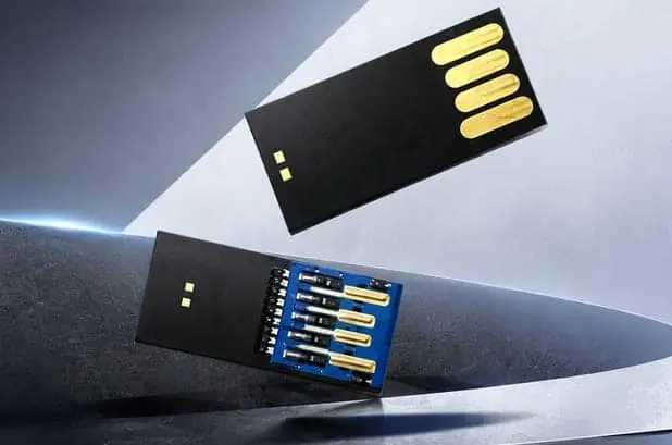
On a module, the interface is a physical fact before it is a logical one. The contact pads on the connector are the interface. A board with four contacts is a USB 2.0 part and 480 Mbit/s raw is its ceiling; the speed class question does not arise because there is no SD bus to mark. Choosing the interface is a PCB decision, made before tooling, and it cannot be recovered later by firmware.
What our published data does and does not carry
Our published product data covers the formats we build and their physical dimensions: the TF card at 15 × 11 × 1 mm and 0.25 g from 4GB to 256GB, the UDP module at 11.3 × 24.8 × 1.45 mm and 0.819 g, and the semi-finished board at 12 × 44 × 4.5 mm and 3.2 g. Those are documented product figures.
It does not publish a speed ladder per capacity, because a speed figure tied to a capacity without a defined test pattern and window is a marketing number. What we will do instead is agree the pattern, the host and the acceptance figure with you in writing, then build the configuration against it. If the number you need is above the published floor for that marking, we will tell you before the tooling is cut rather than after the first shipment.
When both numbers are noise
If your device writes one firmware image during manufacturing and then reads rarely, a 10 MB/s floor covers it. Paying for U3 in that application buys margin nobody spends, and the money shows up in the unit price.
If the socket is USB 2.0, the interface figure is fixed at 480 Mbit/s raw and the speed class marking can change the print on the card, not the throughput behind it. Specifying higher there is a cost with no field effect.
If the write is bursty and short — an event log that writes a few hundred kilobytes at a time — neither the class floor nor the bus ceiling will describe what you see. Cache behaviour dominates, and the only honest number is one you measured on your own hardware.
When you should not buy this from us
Three situations where another supplier is the better answer.
If you need a retail consumer card with a retail channel, local stock and a shop-facing warranty, we are a factory running scheduled production in batches, not a distributor with a shelf. The lead time and the batch structure will frustrate a restock cycle that assumes next-day dispatch.
If you require a named original-brand die with written lot traceability to a specific wafer, we can commit to the format, the package and the interface. We cannot commit to a brand promise we would have to write under a name we do not control, and a factory that signs that without knowing its own purchase plan is guessing.
If you want the lowest price per gigabyte on a part with no custom artwork and no inspection documentation, a commodity market card is cheaper than ours. We price in artwork separation, batch records and the ability to run the test the configuration needs. Without those, you are paying for process you will never use.
What to put in the RFQ instead
Four lines. The sequential sustained write you need, with the block size and the window. The random I/O you need, with the queue depth. The host interface, named as a mode or a socket, not as an adjective. And the acceptance condition — who tests, on what pattern, and what figure fails the lot.
A supplier who reads those four lines back to you without adding a marketing number is answering the question you asked. One who rewrites it as “up to 100 MB/s” has moved the conversation from a floor to a peak, and that is the difference this whole article is about.
Sources
Frequently asked questions
Which number should I write in my specification?
Both, in different sentences. Write the sustained write you require as a measured figure, with the write pattern and the window you measured it over. Write the host interface separately, because that is the number that caps everything. A line that says 'U3' only tells the factory which marking to print. A line that says '30 MB/s minimum sustained write, sequential 1 MB, host UHS-I' is testable, and a testable line is the one that survives a failed incoming inspection.
Does a card marked V30 guarantee 30 MB/s write speed?
It guarantees a minimum sustained write of 30 MB/s under the Video Speed Class definition, not a peak, and not a guarantee once you install it in a host that cannot signal faster than the card. The SD Association sets the figure; the host decides whether you reach it. A card marked V30 in a Default Speed host is still limited by the 25 MB/s bus ceiling, so the marking is true and irrelevant at the same time.
Can a UHS-II card run at 312 MB/s in any host?
No. The bus ceiling is reached by negotiation between the card and the host socket, so a UHS-II card in a UHS-I host falls back to the UHS-I ceiling of 104 MB/s. This is the most common source of a speed complaint that is not a quality complaint: the card is correct, the host is the limit, and the numbers on both sides are accurate.
Why does my 64 GB card read faster than a 32 GB one when both are marked C10?
Because the C10 marking is a floor, not a description of a typical run. Where in the performance range you actually sit depends on the controller, the number of channels it drives, the firmware's cache handling and the pattern your device writes in. Two cards can both meet the same published minimum and differ well above it. That difference is worth measuring if write time matters to you, and it is not worth arguing about at the quoting stage.
Does the speed class say anything about random I/O?
Not the speed class rows. C10, U1 and V30 describe sequential sustained write. Random I/O is the Application Performance Class: A1 is 1,500 read and 500 write IOPS, A2 is 4,000 read and 2,000 write IOPS. If your device boots an interface, opens a database or responds to a UI from the card, A1 or A2 is the marking that matters, and a V30 rating on the pack tells you nothing about it.
Can I get a UDP (USB Disk in Package) module with USB 3.0?
It depends on the board and the contact count, not on the firmware. Under the USB Implementers Forum naming, USB 3.2 Gen 1x1 is the rate most buyers still call USB 3.0, at 5 Gbit/s raw with 8b/10b encoding so the payload is lower than the raw figure. Gen 2x1 is 10 Gbit/s and Gen 2x2 is 20 Gbit/s. A module built with four contact pads is a USB 2.0 part at 480 Mbit/s raw and cannot be upgraded by software, so the interface has to be decided at the PCB stage.